How to Make Almost* Anything | MAS.863
Ella Peinovich | M.Arch Level III, MIT
Ella Peinovich | M.Arch Level III, MIT
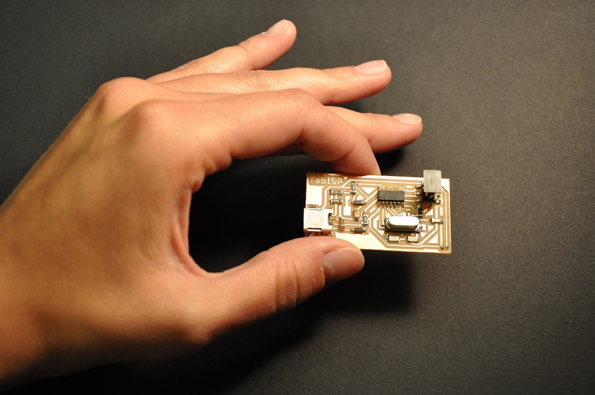
FabISP In-Circuit Programmer
This week we were assigned the task of milling, cutting, stuffing, & programming a predesigned circuit board. It will function as a USB communication for programming microcontrollers on other circuit boards. My process is described here with links to the FabLab tutorials.
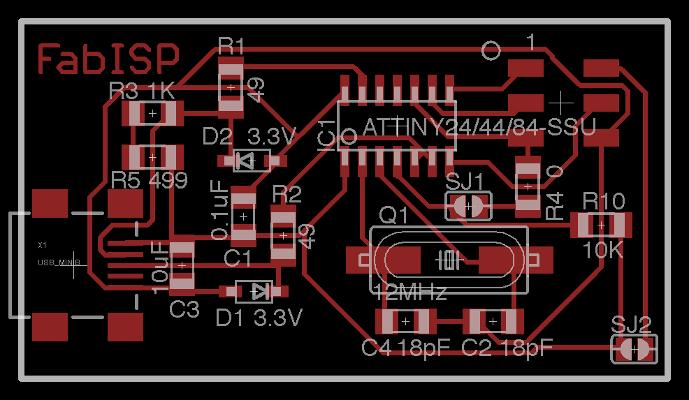
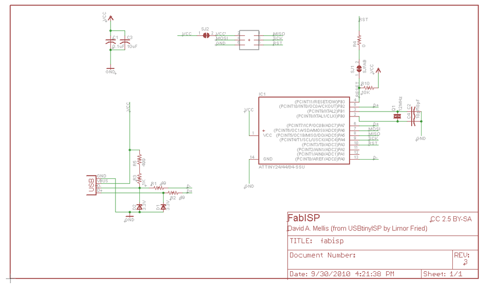
Step 01 | Design (or in this case Download) Circuit Artwork and Schematic
Using Eagle freeware, I was able to view the artwork from which we extracted a PNG file for milling. We were able to later track the size and orientation of components by using the coordinated files. Admittedly, I do not fully understand the complexities of this design, but took a step in that direction.
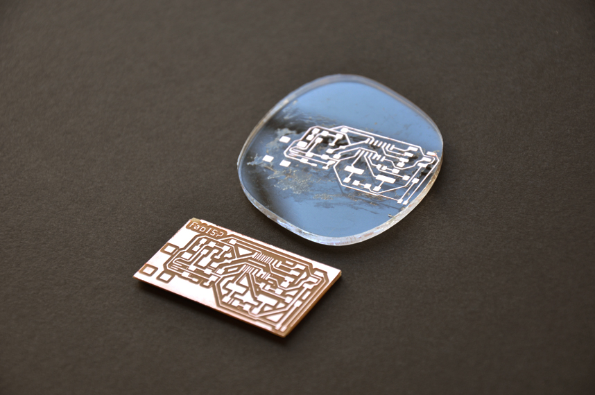
Step 02 | Fabricate Circuit Board
I chose to use both the Modela milling machine as well as the vinyl cutter to test two methods of fabrication. I used Fab Modules to create each of my cut files for the circuit. Only for its robustness did I like the milled circuit. For the purpose of embedding circuits into my final proposal and other architectural applications I feel the vinyl cut circuit would be the most discreet option; because of its flexibility it could eliminate the need for cables and being built into a fixed building component it would not see too much wear and tear.
The process on the Modela mill is described here: modela milling process & on the vinyl cutter here: vinyl cutting process.
Step 03 | Stuff Circuit Board
My first soldering experience went relatively smoothly. At setting 70, I was able to use the technique of tining one pad (iron in one hand and tin wire in other) and then reheating and placing chip into solder (iron in one hand and tweezer with chip in other). I then tacked more securely both sides with additional solder. I was able to test my initial solders with the multimeter, to be sure all connections were secure and not bridging unwanted connections.
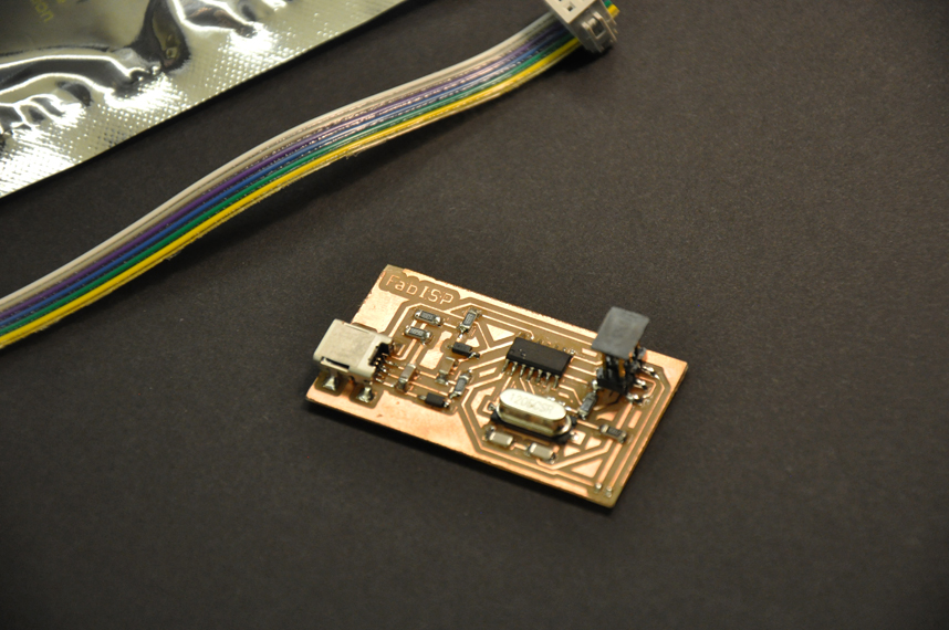
Step 04 | Program Circuit Board
SUCCESS! As a true testiment to my soldering skills, I was able to configure the board without needing to debug; this was confirmed by seeing that it self-identified as a USB when plugged into my computer. I can now configure my future microcontrollers and even other FabISP boards using just a USB cable and IDC cable. This process is further described here: program microcontroller.